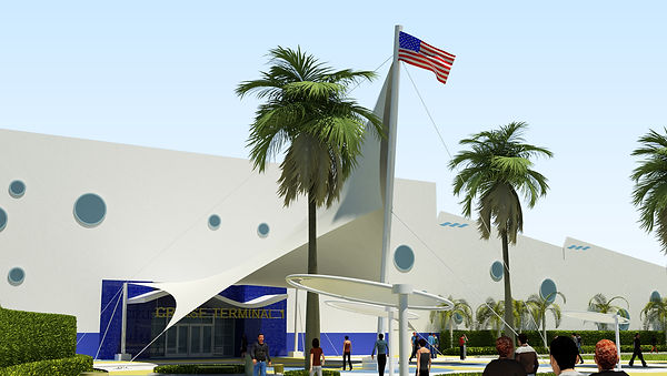
Canaveral Port Authority Cruise Terminal 1
Port Canaveral, FL
Joseph Kramer | Mechanical Option | Advisor: Dr. William Bahnfleth

Rendering courtesy of BEA Architects
General Building Data
Part 1
General Information
Building Name: Canaveral Port Authority Cruise Terminal 1
Location: Cape Canaveral, FL
Site: Port Canaveral
Building Occupant Name: Canaveral Port Authority
Occupancy and Function Types: A-3 Assembly (Transportation Terminals)
Size: 188,514 Square feet
Number of Stories Above Grade: Two
Owner: Canaveral Port Authority http://www.portcanaveral.com/
General Contractor and CM: Ivey’s Construction http://iveysconstruction.com/
Architect: BEA Architects, Inc. http://www.beai.com/
MEP/Structural Engineers: TLC Engineering for Architecture http://www.tlc-engineers.com
Site Preparation Engineers: Allen Engineering http://www.alleneng.com/
Dates of Construction: December 11, 2013 – November 2014
Total Construction Cost: $50.5 Million
Project Delivery Method: Design-build
Architecture
Architecture: Cruise Terminal 1 is a mixed use/assembly type building that regularly hosts around 5,000 occupants. Designed by BEA Architects, this 2 story terminal is used as a gateway for eager vacationers to board their cruise ship. Upon entry, visitors experience a 2 story tall main lobby, then can proceed to the large baggage lay down area. The baggage inspection are is on the eastern side of the building, and allows the passengers to board their ships. The second floor of CT-1 mostly consists of an additional seating area directly above the ground floor baggage lay down area.
Major National Model Codes: Florida Building Code 2010, Life Safety Code NFPA 101 2009 Edition
Zoning: 11 story maximum height and unlimited area
Historical Requirements of Building: Not applicable
Building Enclosure
Building Facades: CT-1 employs aluminum framing on all windows, which are given impact glazing to resist Florida’s rough hurricanes. The east façade of the terminal is constructed with a ribbed metal wall panel on top of a vapor barrier and 5/8” exterior wall board. On the South façade, there exists a tilt up, concrete exterior wall with a textured coating. The North façade contains seven garage doorways which take away from a potentially appealing view. The West façade is by far the most dynamic, for it serves as the main entry way to the terminal. There are a plethora of circular windows placed on the West façade, giving the visitors an aesthetically pleasing view.
Roofing: The roof of CT-1 includes a thermoplastic polyolefin roofing membrane that reduces solar heat gain by reflecting the sun off of the roof. The roof has a long gradual downslope towards the south of the building complete with roof drains to compensate for Florida’s heavy rain.
Sustainability Features
Cruise Terminal 1 implemented LED light fixtures on the building interior, exterior, and in the plaza in order to cut down on electricity consumption. The outdoor air handling units utilized energy recovery wheels to save energy as well. CT-1 also uses a thermoplastic polyolefin roofing membrane which reflects the brutal Florida sun off of the roof, reducing solar heat gain.
Part 2
Primary Engineering Systems
Construction:
The project delivery method for CT-1 was design-build, and the construction was managed by Ivey’s Construction, who was also the general contractor for the project. The site was first prepared by Allen Engineering, where it was then turned over to Ivey’s Construction. The site logistics was fairly simply to plan, due to the wide open site area. Large construction equipment, such as cranes and dozers, was able to move around the site quite easily. As shown in the time lapse video of CT-1’s construction, the concrete slab floor were laid out first, then the tilt-up concrete walls were set into place, along with the second floor and roof. The construction of CT-1 lasted from December of 2013 to November of 2014, and the total project cost was $50.5M.
Electrical:
The Canaveral Port Authority utility feed supplies power to CT-1’s FPL transformer, which connects to a 4000 Amp, 277/480V, three phase main switchboard and a 1200 Amp, 277/480V, three phase secondary switchboard. The main switchboard encompasses the majority of the first floor, the warehouse, and the outside, while the secondary switchboard encompasses the plaza and the second floor. There are a total of 36 panelboards within CT-1, 17 being 120/208 Y, and 19 being 480/277 Y. A 2.25 MW gas powered generator will supply the building electrical systems if primary power is unavailable.
Lighting:
CT-1 is classified as a convention center, which has a maximum lighting power density (LPD) of 1.2W/SF as dictated by ASHRAE 90.1. CT-1 complies with ASHRAE, as it has an internal lighting power density of 1.1 W/SF. In order to save energy and cost, CT-1 employs a variety of LED lighting fixtures throughout the building. The main entry lobby utilizes 54W T5HO surface mounted cove lights and high bay LED lighting fixtures in order to give the proper illumination for a grand entrance. The CPB office area includes grid mounted fluorescent troffer and decorative linear pendant mounted fluorescent lighting fixtures in order to supply adequate task lighting for office activities and for inspection. In order to illuminate the large debarking area, CT-1 utilizes industrial fluorescent strip fixtures, while the large waiting area on the second floor uses recessed LED downlights which save on energy costs.
The building automation system within CT-1, provides ON/OFF control for all light fixtures connected to the contactor. Occupancy sensors providing additional lighting control will be provided in the office areas.
Mechanical:
CT-1 is serviced by 15 rooftop units (RTU), 4 designated outdoor air units, and 33 split systems. RTUs 1 through 4 serve the main entrance lobby and greeting area, RTU 5 services the CPB area via 14 VAV terminal units, RTUs 6 and 7 supply the debark area, RTUs 8 through 14 supply the second floor waiting area, and RTU 15 handles the vestibule on the first floor. All RTUs are direct expansion systems. The split systems are mostly used to heat and cool the passenger bridge on the east side of the building, and some are used for the various electrical rooms. Most of the RTUs do not meet the required outdoor air ventilation rates set in ASHRAE 62.1, so the 4 outdoor air units (OAUs) are used to supply makeup air. OAU 1 makes up for the lobby area, OAU 2 makes up for the debark area, OAU 3 makes up for the second floor waiting area, and OAU 4 supplies all of the ventilation for the warehouse. The four OAUs utilized for CT-1 are equipped with energy recovery wheels in order to save energy. The outdoor air conditions set for CT-1 are 93.5°F dry bulb and 78.6°F wet bulb, and the indoor set point is 75°F/55% RH for the cooling season and 70°F/50% RH for the heating season. The primary air distribution method for CT-1 is through the ceiling plenum which is an effective choice for this climate.
Structural:
The superstructure of CT-1 consists of 7-1/4” thick tilt up concrete panels along most of the exterior, and has 9-1/4” thick tilt up concrete panels at the main entrance on the West façade. 7-1/4” thick tilt up concrete panels are used in the building interior as shear walls. The Foundation of CT-1 includes pile extending both 85’ and 65’ below the mean low water level with 85 and 65 ton capacities respectfully. The slab on grade is a 6” thick concrete slab reinforced with W/ 4x4 W2.9xW2.9 WWF on 15mm vapor barrier. The second floor framing consists of mostly W12x144 beams with 3/4” camber for the passenger bridge and waiting area, and W12x14 beams for the balcony. Above the CBP Area, 24K10 joists @ 5’ O.C. are used with W18x35 girders with 1/2” camber. The roof deck is 1-1/2”, 20 guage, Vulcraft CSV with type II insulating concrete held up by 24K7 joists and W21x48 girders over the large waiting area, and 24K5 joists with W18x35 girders over the lobby area. Because CT-1 is located on the East coast of Florida, an area with frequent hurricanes, it was given a rain load of 25PSF, exposure category C, risk category III, and utilizes an ultimate design wind speed of 160MPH.
Additional Engineering Support Systems
Fire Protection:
The fire protection for CT-1 complies with NFPA 13, 14, 20, and 24. The occupancy for most of the building is classified as light hazard, and the storage/mechanical/electrical rooms are classified as ordinary hazard group 1. The entire building is protected with an automatic wet standpipe system, and the light hazard group will receive .10 GPM/SF, while the ordinary hazard group 1 section will receive .15GPM/SF. The duration of supply for the entire building is 60-90 minutes to allow for proper evacuation and fire suppression. The maximum coverage per sprinkler heads are 225SF for light hazard, and 130SF for ordinary hazard group 1.
Transportation:
CT-1 employs a three-lane escalator and two elevators in the lobby, two elevators in the large debarking area, and six exterior staircases in order to keep the occupants moving at an acceptable rate. The large escalator in the lobby deal with the highest volume of occupant traffic, as it is responsible for moving people from the large waiting area to the debarking area. A parking garage is located on the site, which accommodates the many guests who arrive at the cruise terminal. The site also includes an East and West bus loop to allow for quick and easy traffic flow.
Telecommunications:
The telecommunication drawings for CT-1 are not available at this time.
Special Systems:
CT-1 utilizes a thermoplastic polyolefin roofing membrane which reflects the hot Florida sun off of the roof, reducing solar heat gain.